
Intro
This will be an ongoing information dump as I progress along on this super commuter project. My goal is to create a relatively (<45lb) commuter cargo bike with full suspension elements. I like to ride up and over Montebello -> Black Mountain in Los Altos on my way to work, and sometimes take the Indian Creek trail (starting at Steven’s Canyon) up or down. This is a pretty treacherous route to bomb along on a rigid bike with 15-30lbs of cargo in the front basket. I’m excited to add some real suppleness to my ride.
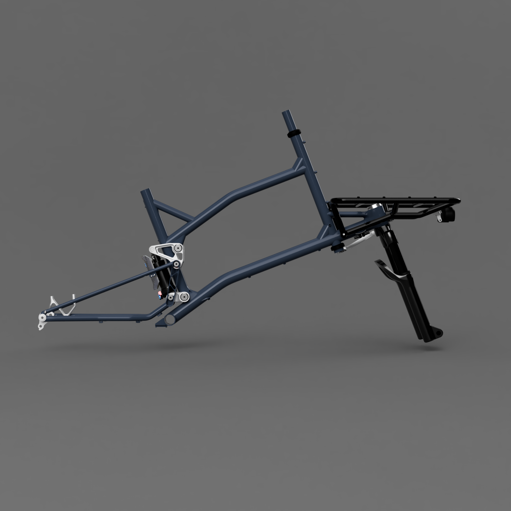
The frame should be relatively compact (wheelbase between 1250 and 1350mm) and be a fun application for laser-cut tubing and SUS 3DP parts to save time and fabrication hassle. I’m leaning towards a counter-rotating dual-link layout for the rear with a shock suspended between the upper and lower links. I want to place the shock behind the seat tube to allow for long droppers (un-interrupted by a seat tube bend) and create plenty of front triangle space for mounting cool stuff like bottles and frame bags. This is a layout I haven’t seen done with dual links and I’m excited (and nervous!) to see how it performs in the real world.
My plan is to use a staggered wheel setup with 24” rear and 20” front. My hand was forced towards a small front wheel as I wanted a front loading cargo frame with a low cargo deck; wheel sizes >20” push the cargo load high and create interferences with handlebars. I’ve almost fallen a few times on my other cargo bikes where my handlebars hit bags and boxes after ~10° of steer angle and lock up. I chose a 24” rear wheel for a few reasons:
I run 24” on my commuter bike and love how responsive it feels while having good rollover capability on rocky terrain
24” looks aesthetically balanced with 20” wheels (to my eyes at least!)
24” rear wheel enables me to run a rear-mounted, fully-suspended shock that lives between the upper and lower rocker links
Modeling:
I tend to alternate between tweaking my kinematic layout in Fusion 360 and graphically calculating various responses in a program like Matlab. Fusion is a great tool for constraining/defining your overall design space for a given suspension layout. By dimensioning/constraining certain sketch elements, I ensure I am hitting a threshold shock stroke, vertical wheel travel, maintaining component clearance, and am in the general vicinity of my target kinematic responses.
I’m no authority on what kinematic parameters should be optimized for a bike frame, particularly a front-loading cargo bike. I tend to mash my pedals hard and really dislike bob on full-suspension bikes I’ve ridden with low (<<100%) Anti-Squat numbers. I found the counter-rotating dual link layout yields pretty stable Anti-Squat numbers throughout my entire cassette/gear range with my estimated COG height. Some graphs are shown below.
I’m using a simple Matlab program to calculate my various responses. I use the vector loop approach to define my rear swingarm (assuming my front triangle is static, though the front wheel/fork is allowed to move along its telescopic path). I know my shock will be directly driven by my upper link in the dual link layout and can define the upper link’s rotation range based on my Fusion kinematic sketch and whether the shock is to the left or right of the upper link pivot point.
From there, I create a Jacobian matrix of my vector loop for my unknown link angles and multiply the inverse Jacobian and scalar position vector. I subtract this value from my initial/previous guess of unknown joint angles. This process is iteratively repeated (Newton’s method) until a certain error threshold condition is met. Tbh, I don’t need this to be accurate within a few µm, so each iteration cycle is only a few runs and the overall program seems pretty efficient.
MatLab script below. I’ll try to update this as I add more functionality to the tool but the bones are there! Honestly, with how good AI tools are now, you can probably create something way more powerful than this in a few hours if you're patient and motivated.


Concepts:
Sooo… Concepts? I played around with a few different layouts to try to find something I liked. I’m not a huge fan of the huge cantilevered front rack - I don’t think this meshes well with my riding style and cargo loads. Moving towards an extended front end made sense to me. Some ideas I tried but couldn’t find a strong justification to keep:
Pinion gearbox - oh man, I love the idea of a C1.9 with Gates belt drive and virtually eliminating drivetrain maintenance. However, the system is incredibly expensive and space restrictive when placing links and routing frame tubing / members. I’d love to revisit this at a future point. However, I don’t think my wallet or packaging ability is up to the task of working with a Pinion just yet.
Belt-drive front steering - I think this is an awesome idea and love MonoPole’s implementation on their cargo bike. However, I was scared by the idea of developing a robust way to tension / maintain tension on the belt system and establish an intuitive ride feel. I don’t think this is something I’d achieve 100% on the first go-around. I can run a rigid-link steering arm with Enduro bearings and still achieve 60°+ steering in either direction. This is the route I plan to take.


Frame Fixture:
First up is my new rolling fixture stand. This stand allows me to quickly mount different welding fixtures and Park Tool clamps to hold in-process frames during the welding process.
The rolling stand is comprised of a few 15-series extrusions courtesy of T-Nutz. There is a slider carriage that moves along the vertical extrusion by using 608-bearings tensioned via eccentric cam adjusters (very similar to the v-slot roller 3D printer designs). The vertical carriage has a large rotary plate that can be rotated 360° and locked in any rotation with two spring-loaded toe clamps. I really like the way this turned out!
There is also a hidden gas strut in the vertical extrusion that provides around ~30lbf of lift assistance across 16 inches of vertical stroke. The gas strut is connected to the slider carriage via a braided lanyard running up and over a pulley bolted to the top of the extrusion.
I also added an argon back purge manifold that directly mounts to one side of the slider assembly. Hopefully this helps me quickly plumb various fixtures for back purging (super helpful when welding SUS316L 3DP parts and ER312 or WeldMold 880 filler rod).


