

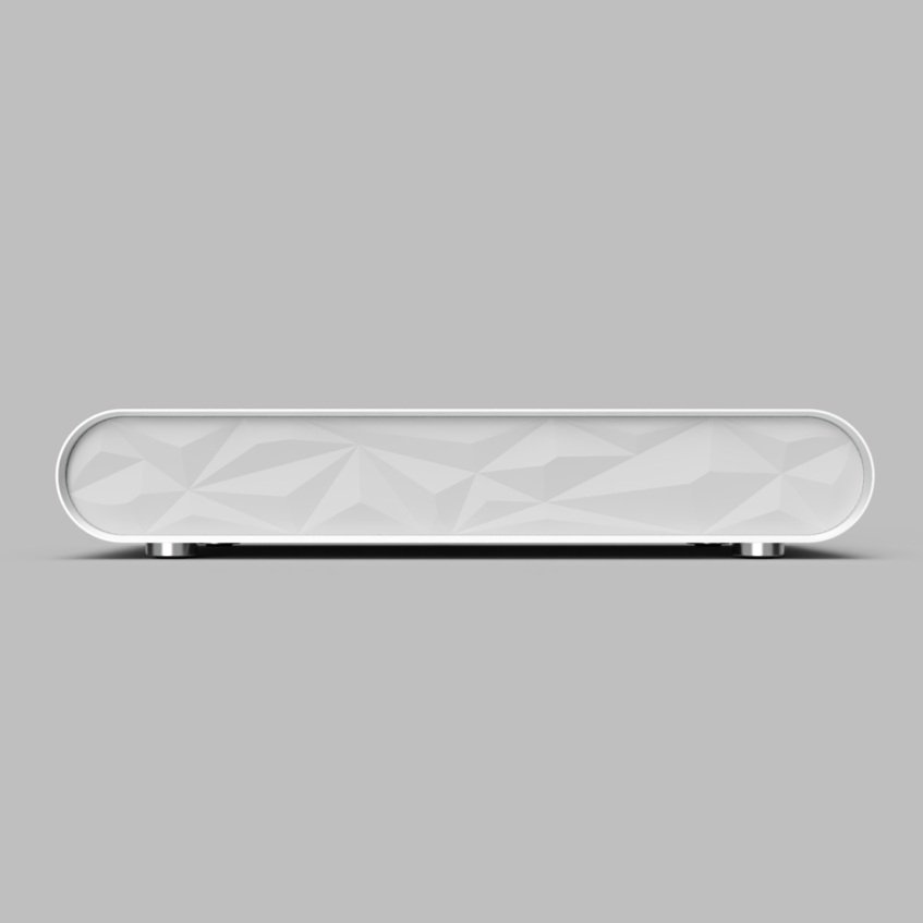
ROUNDI
Roundi (placeholder name) is a new, CNC-machined computer case I am designing and prototyping. My design goal is to create an elegant, aesthetically-pleasing enclosure that echoes Bauhaus design cues. Designs like the Braun SK-2, pictured below, serve as great inspiration.

Braun SK-2. To me, it’s a beautiful, timeless design.
I’ve designed the case around the HD-Plex 250W GaN power supply and an ITX-sized motherboard and graphics card. I prefer to design around ITX-sized components for several reasons:
Size. Processes like CNC machining are resource-intensive, both in terms of raw material and machine time. Small form factor cases require less material than a traditional mATX or ATX tower and are usually more economical to prototype.
Efficiency. I want the portability a SFF case affords and like the look of an assembled system that maximizes the enclosure space.
Challenge: It’s tough to accommodate large (it’s all relative!) and hot components in a small area. I think this makes for a fun design challenge.
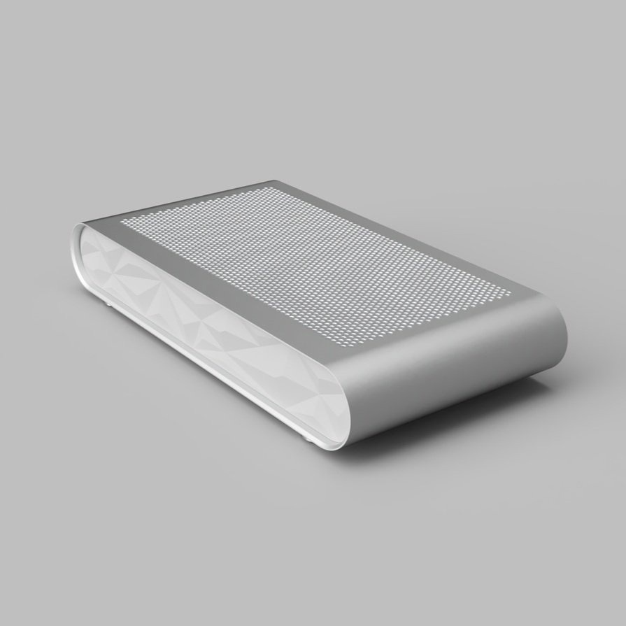
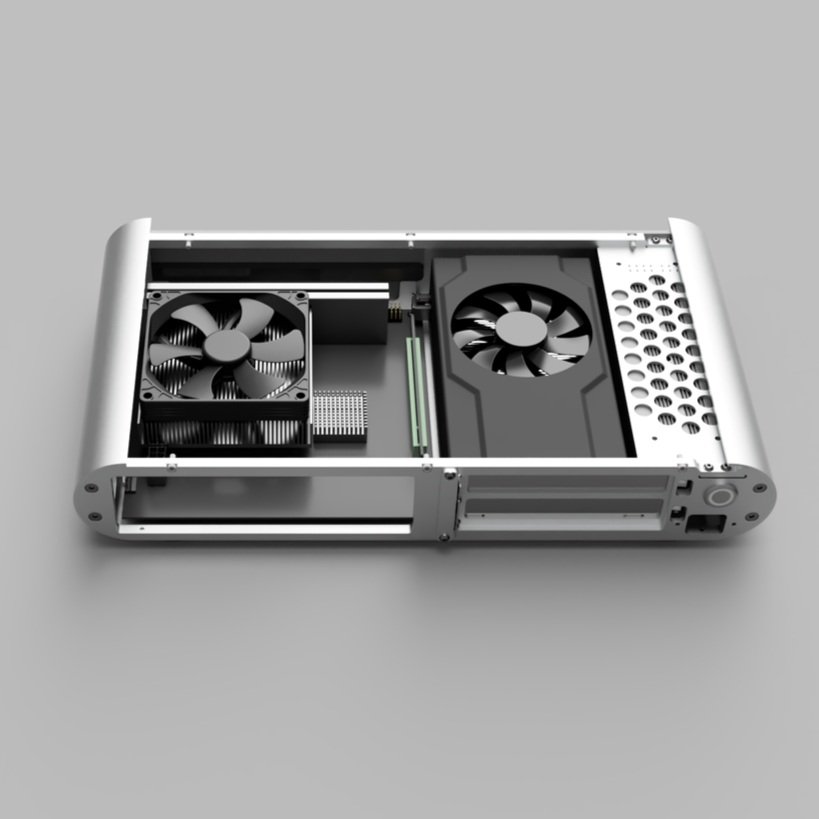
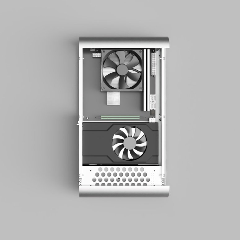
Below is a diagram of Roundi showing the enclosure’s overall dimensions and components. I will keep adding to this page as time goes on.

My fixture system sucks!
I apologize for the terrible pun. This case is comprised of multiple panels that are both large in footprint and thin. Traditional workholding methods like a vise or toe clamps wouldn’t do a good job of constraining the panel during machining; you’d likely see chatter in the the panel far away from each clamp. Our savior? Vacuum workholding!

I found a Mitee-bite VM300 system in the shop that had laid, forgotten, outside for several years. I designed and machined a pallet that goes on top of the VM300 plate with several different-sized gasket grooves, Mitee-bite clamp pockets, and various other workholding features. My pallet also includes a vacuum passthrough that can be plugged with a sealed screw.
Learning!
I learn something new every time I machine! Below I’ll go over a few of my takeaways from this project.
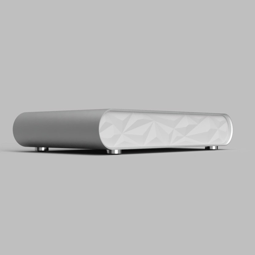
Front Panel
I roughed the front panel out of a 2.5x.5” aluminum bar and pulled vacuum to hold the panel while machining the faceted polygonal pattern. My first run used a scallop toolpath and left a sizeable ridge in the center of the panel. I wasn’t able to get rid of this mark by modifying the toolpath. For subsequent parts, I switched over to a parallel toolpath. Unfortunately, the parallel toolpath also left a pretty poor finish. I’d wager this poor finish was caused by uneven tool engagement (the ball endmill is constantly plunging) and switching between climb/conventional milling on each pass.
The solution? Morphed spiral toolpath to the rescue! I spent an hour trying failing to create what the morphed spiral toolpath created in seconds. The resulting toolpath moves from the outside-in tracing the overall silhouette of the panel in constant stepovers. The final pass is a straight line down the center of the panel.
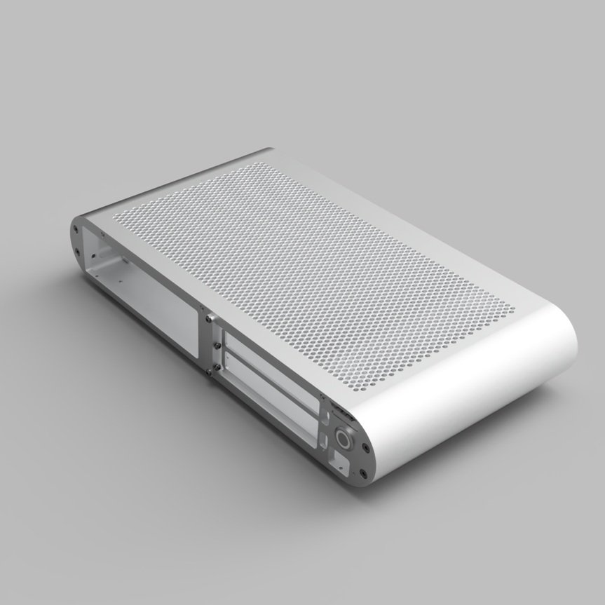
Rear Panel / Front Bracket
The first rear panel I made served as a great reminder on the importance of workholding / part rigidity while machining. I tried to face the rear panel after machining out the IO shield cutout. Unsurprisingly, the panel lost most of its rigidity, resulting in a chattery, poor finish. This problem made me rethink my machining strategy for the rear panel and front bracket. I settled on machining the panel cutouts last, after all of the other features have been machined to final size/shape.
Machining the cutouts last maximizes the part rigidity in all other subsequent operations - this rigidity helps me hit tighter tolerances and achieve better surface finishes. I also used several flanged screws (with nylon washer to avoid marking the part surface) to secure the panel around the cutout area. This increased workholding power resulted in a better cutout finish compared to my first attempt. I call this a win-win!