
The Layout:
There is an overwhelming amount of unique full-suspension bike designs. I ultimately chose a single pivot layout to simplify the design and fabrication stages while retaining good riding characteristics.

Early in the design process, I recorded the geometry numbers of any mountain bike whose appearance or ride characteristics appealed to me. Based upon these numbers and my planned component geometry, I came up with my own geometry values. After this, I made a 2D model of my bike in Fusion 360 in order to determine important geometrical constraints.
I used my Fusion model to create a MATLAB program that calculates the anti-squat, anti-rise, pedal-kickback, and leverage ratio of the bike throughout its travel range, using vector loop analysis methods. The program also calculates the necessary rear triangle geometry based on your desired travel and the location of your front shock eyelet. Finally, the program uses root-sum-square optimization in order to calculate the main pivot location based on user-selected values for anti-squat, anti-rise, and pedal-kickback over specific ranges of travel (in my case, this was around 30% sag).
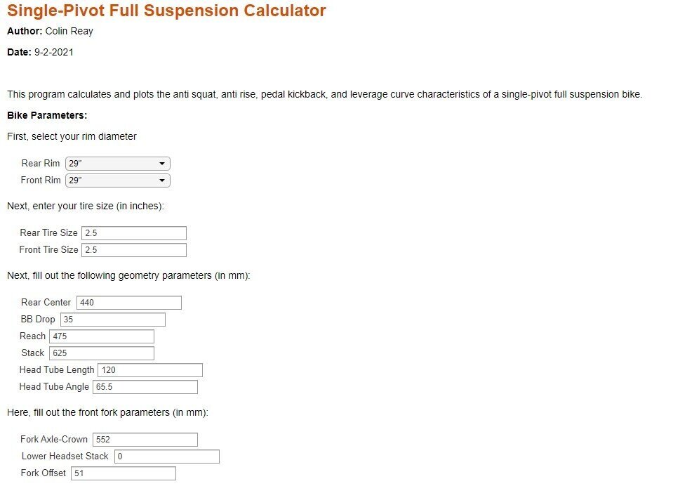
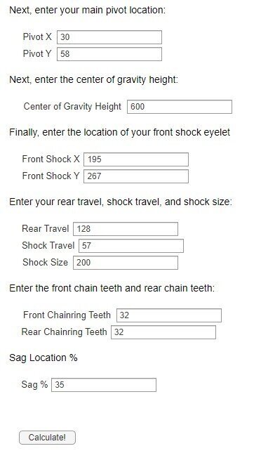
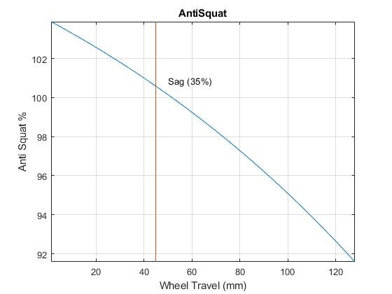
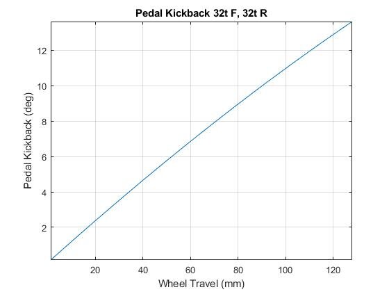
Here is the program UI used to calculate the various suspension responses. Additionally, the geometry of the rear triangle (initial rear shock eyelet position) is also calculated. The results are plotted below.
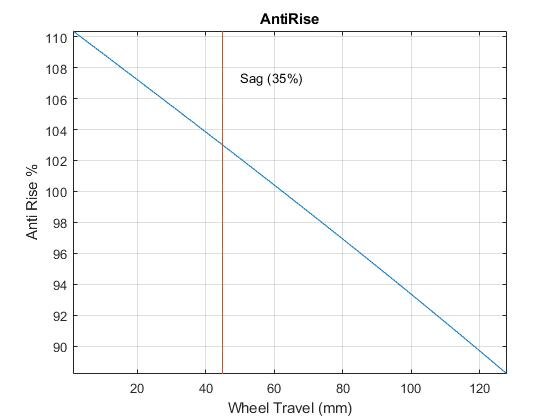
Program outputs
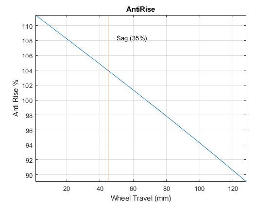
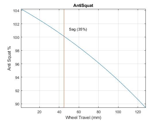
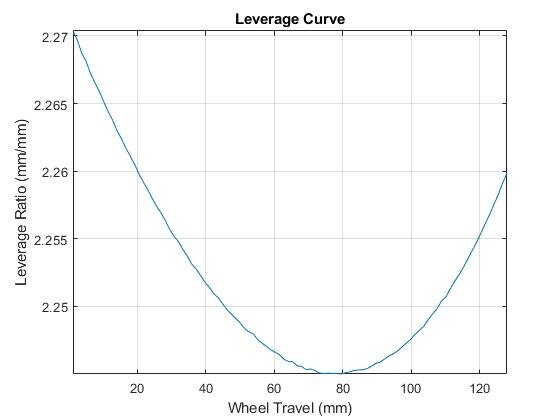
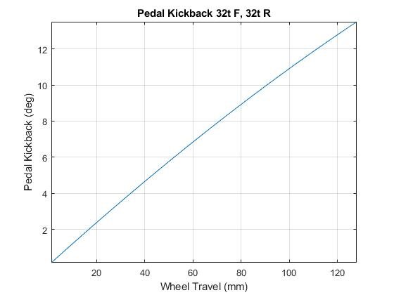


Next, the main pivot point is found through optimization based on desired AS, AR, and PK responses over a specified travel range. As you can see from the output, the actual pivot position is close to optimal.
Optimized Suspension Response
Here, you can download a .zip file of the MATLAB program, including all necessary helper functions. Only edit mainfun.mlx.
I finished the MATLAB program after deciding upon my suspension system geometry using a 3rd party program called Linkage. However, the results of the MATLAB program agree with and validate my design choices based on the Linkage output. After this, I created a full 3D model of the bike frame. I then used this model to create welding fixtures for the front and rear triangles out of aluminum extrusion and machined plates/brackets.

More Modeling Applications
Using methods similar to my MatLab program for single pivots, I developed a program that calculates wheel path, AS, and AR for virtually any 4-bar style linkage and animates the response. Several animations of different types of 4-bar linkages are shown below.
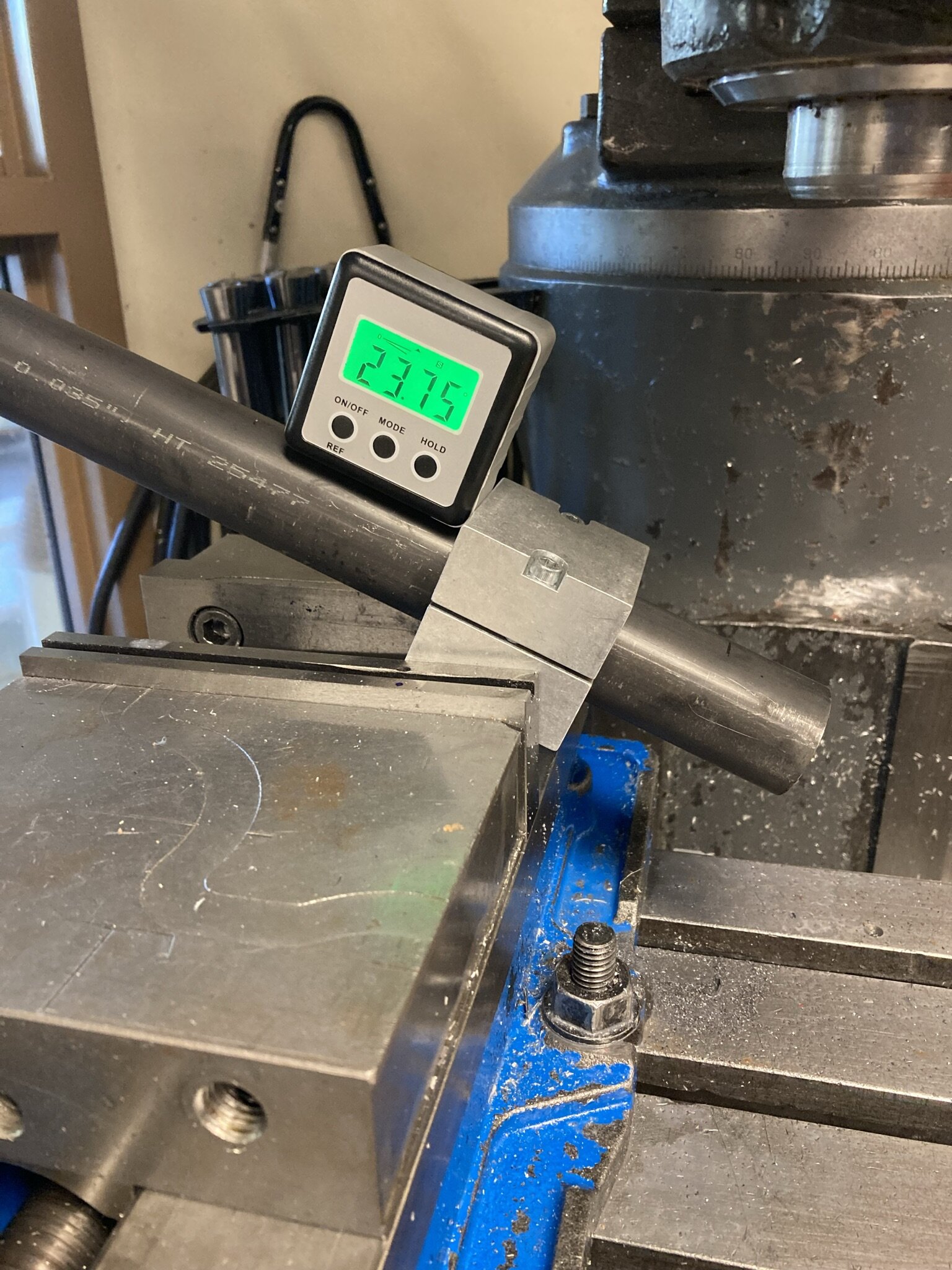
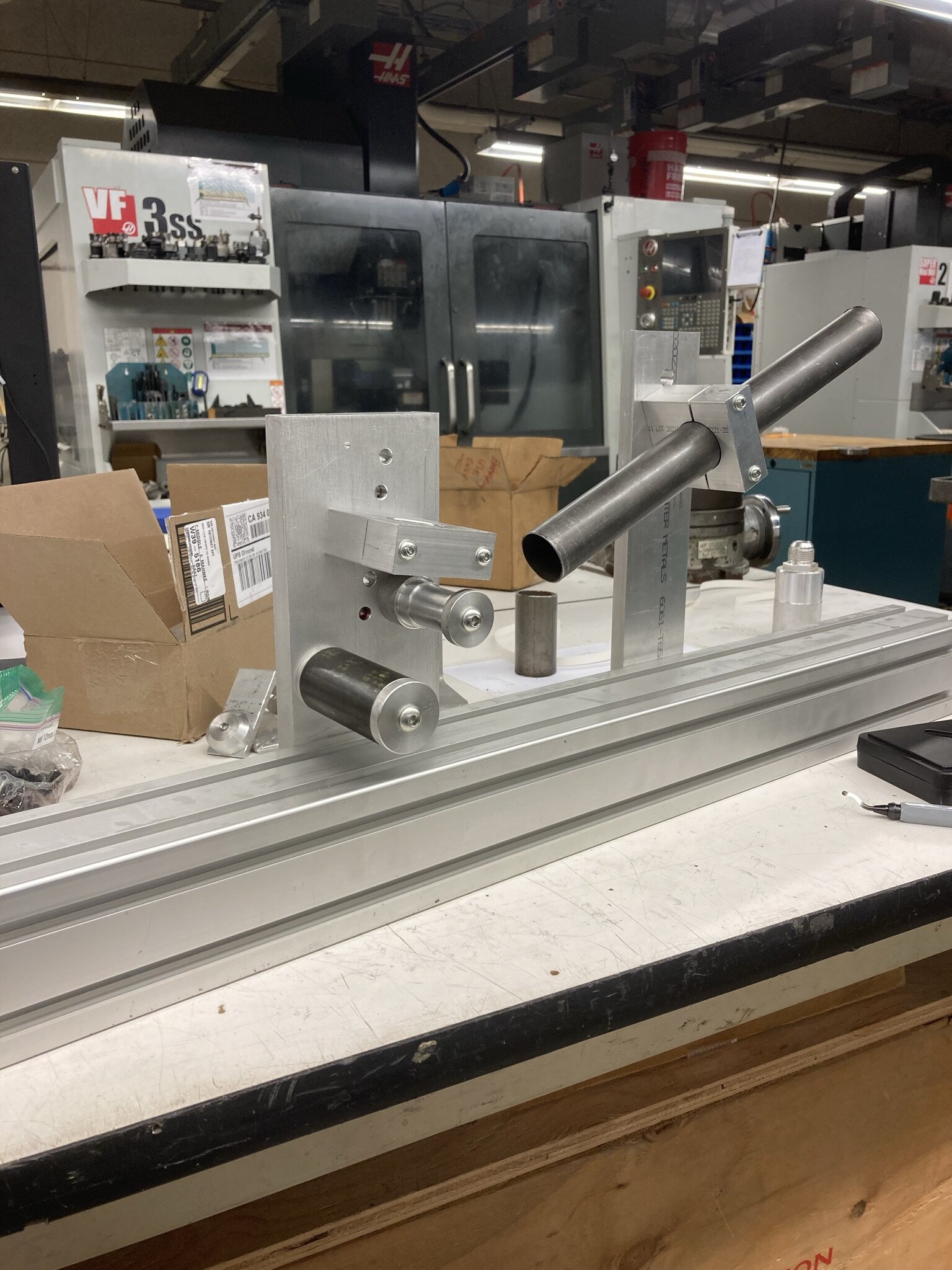
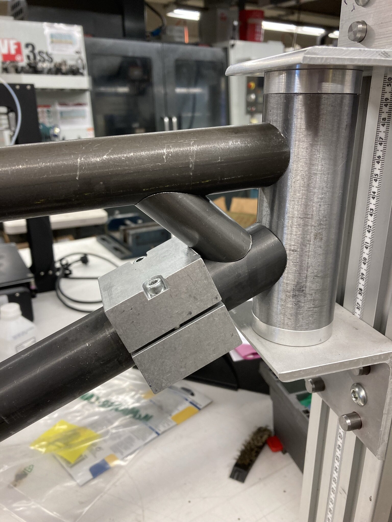
The Rear Triangle
Creating the rear triangle and its welding fixture was rather tricky and required machining many parts out of 6061/7075 aluminum and 4130/4140 Chromoly. I ultimately decided to use an extrusion-based system with split-mounts to locate various tubes and pivot points.


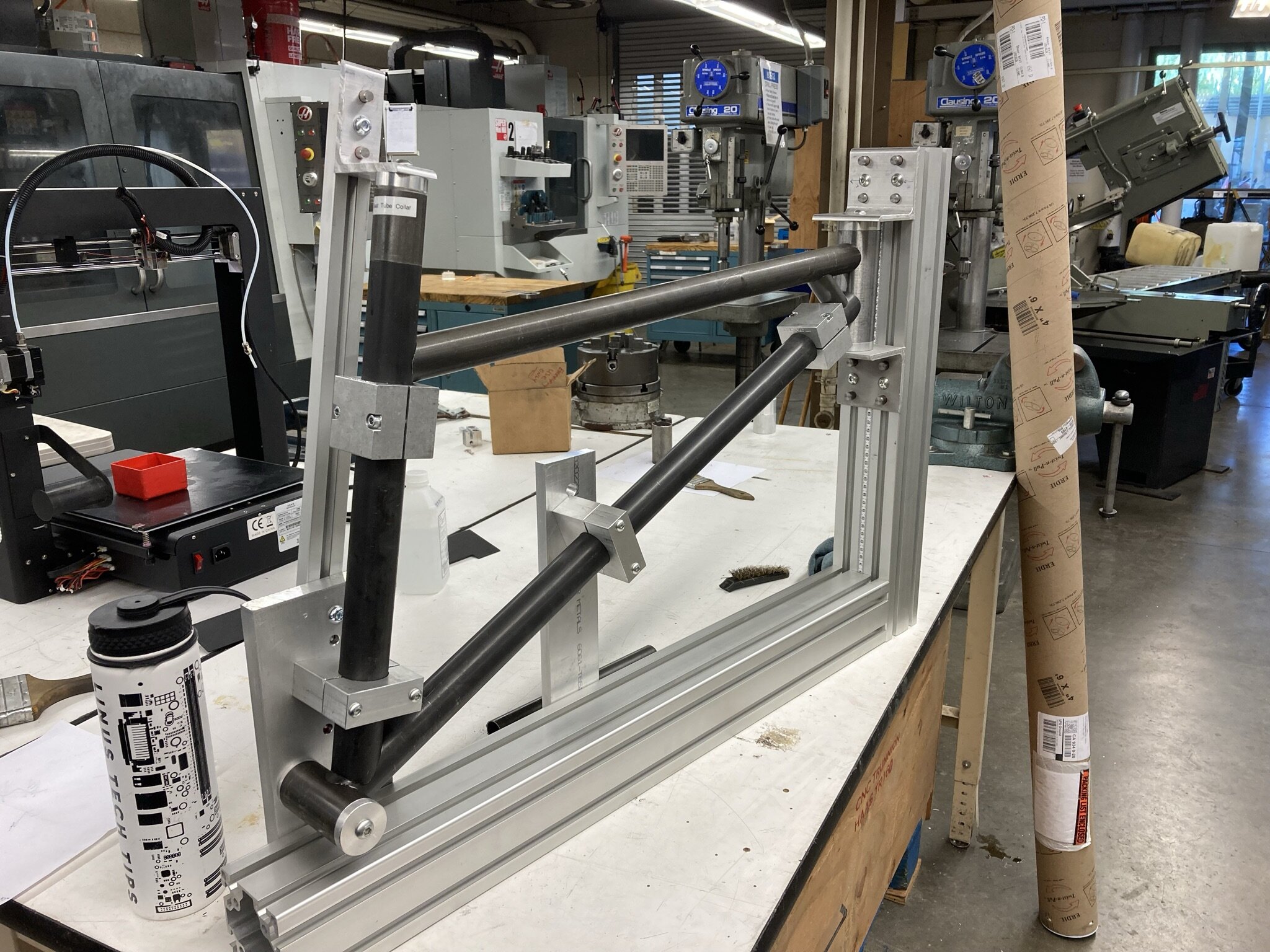
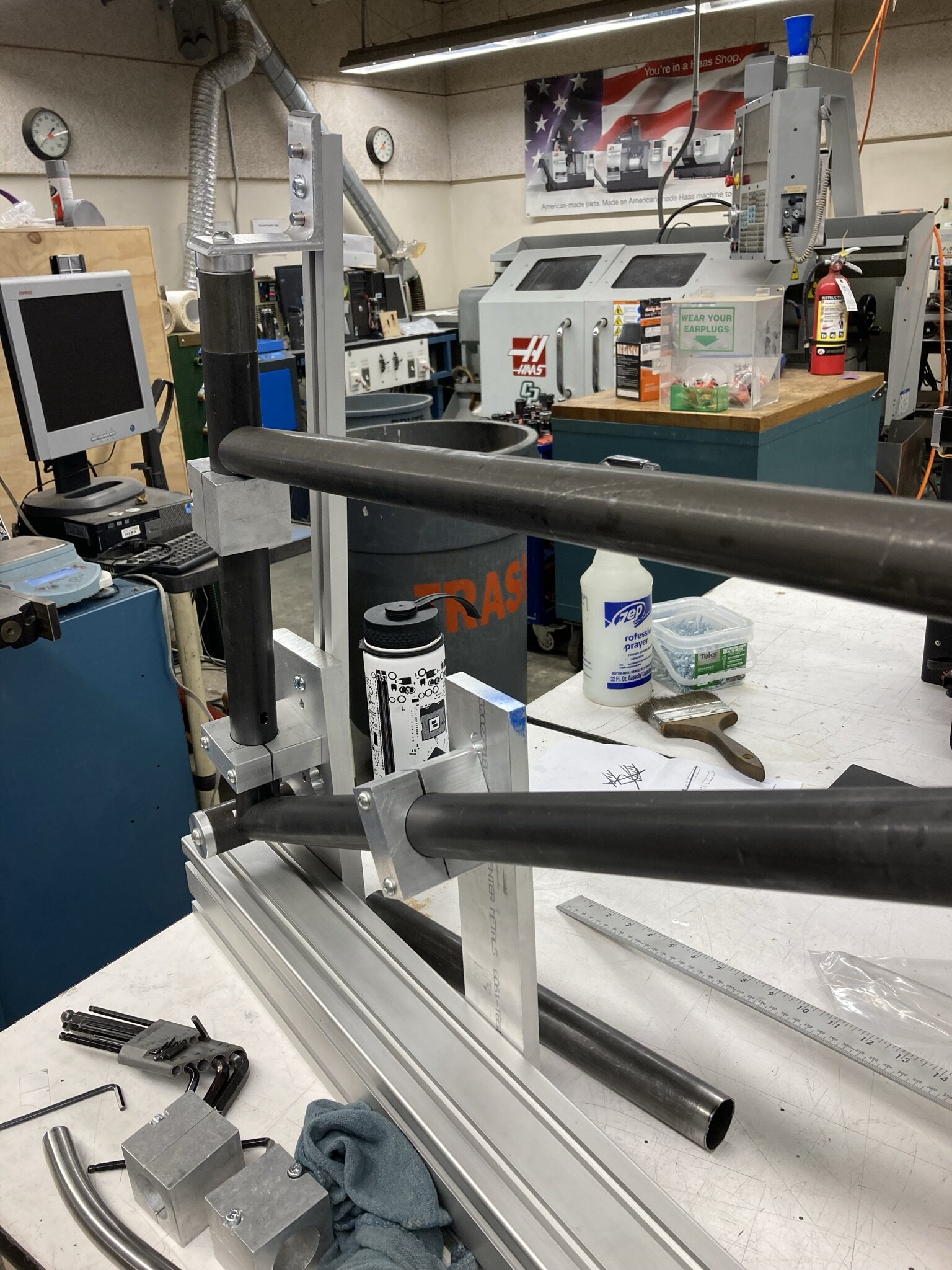
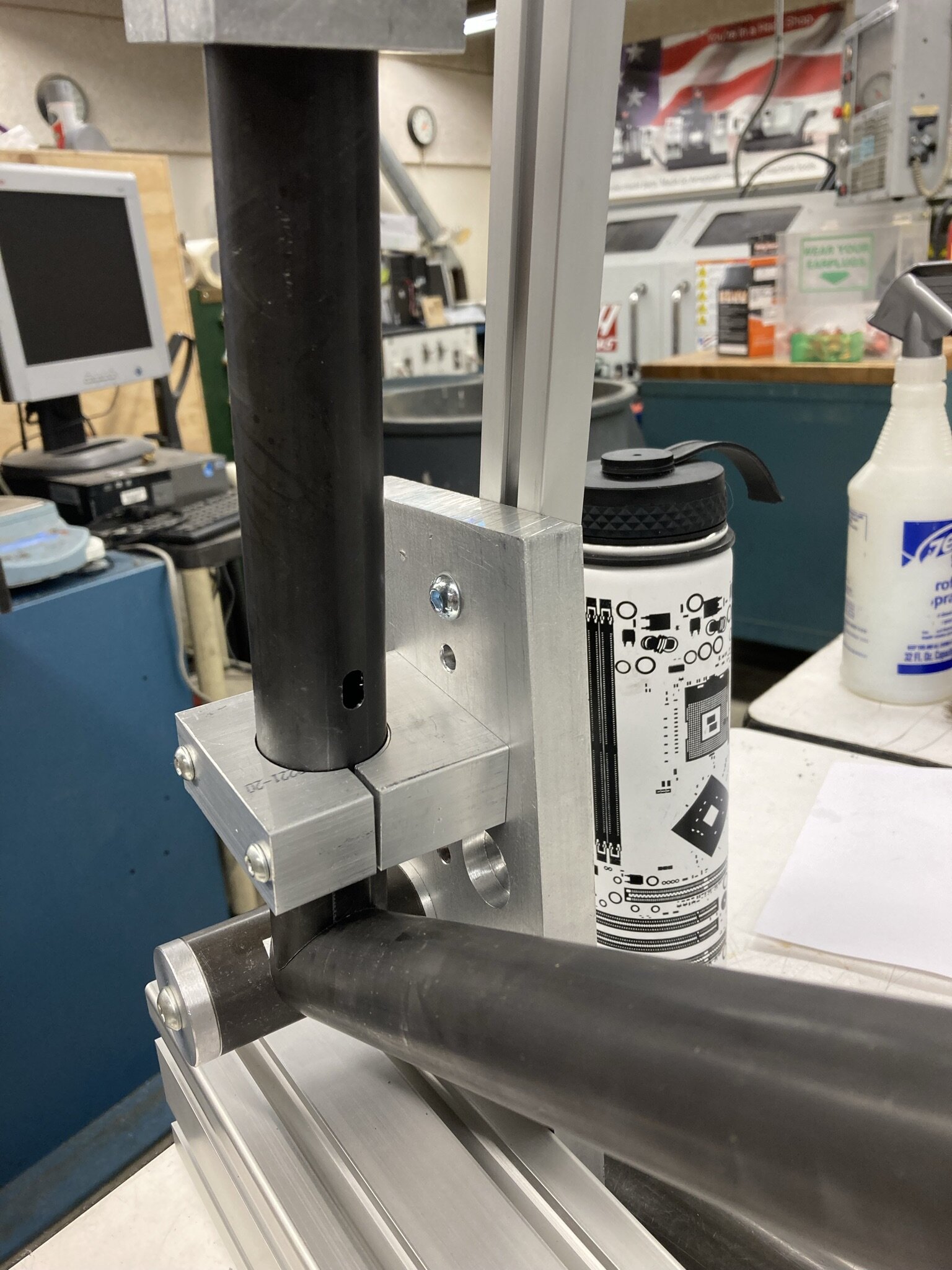
The Front Triangle
Similar to the rear triangle, I created a fixture system using aluminum plates, brackets, and extrusion. I used dowel pins in order to align the mounting plates to the extrusion slots and turned standoffs to locate various hard points.
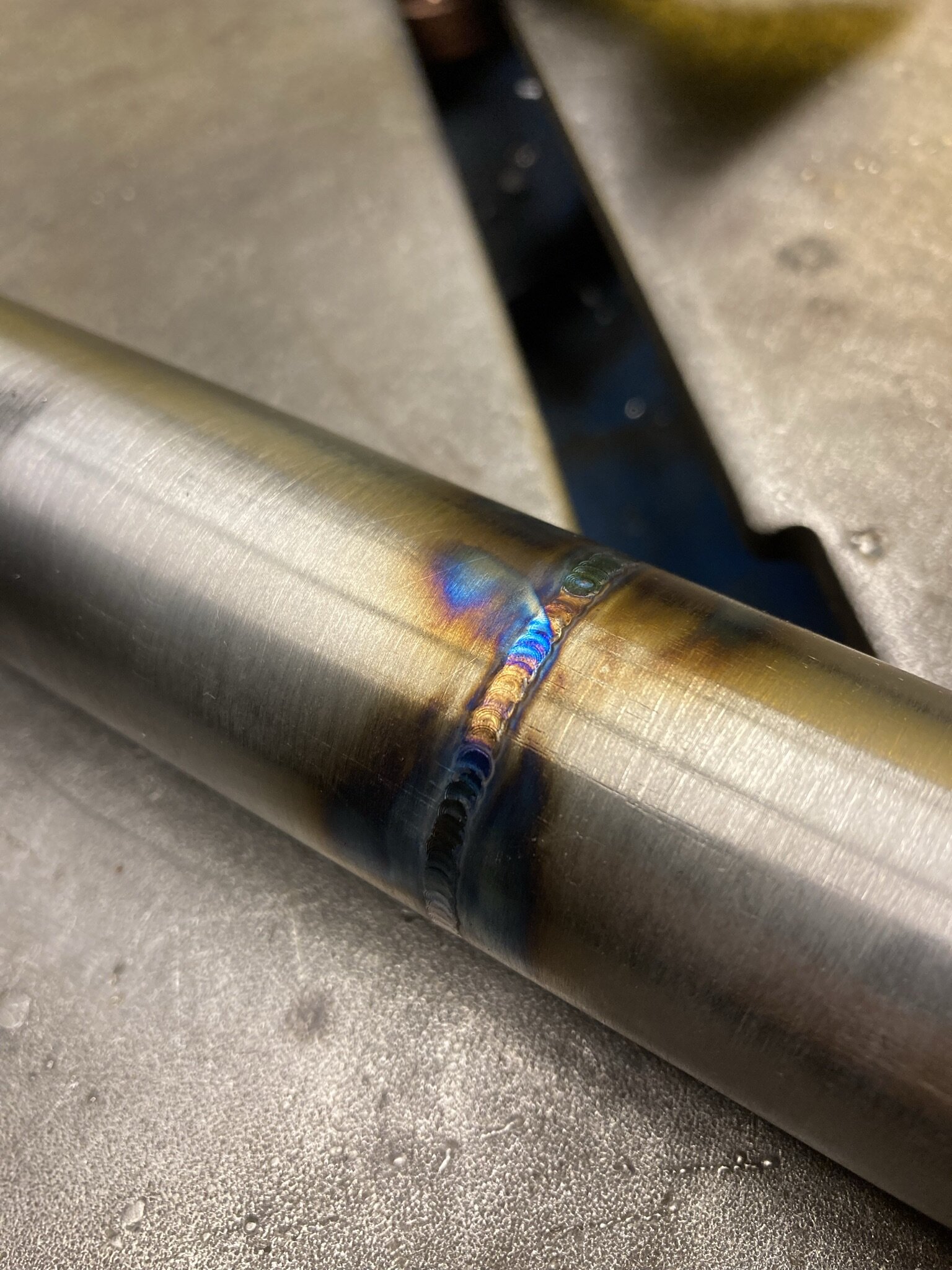
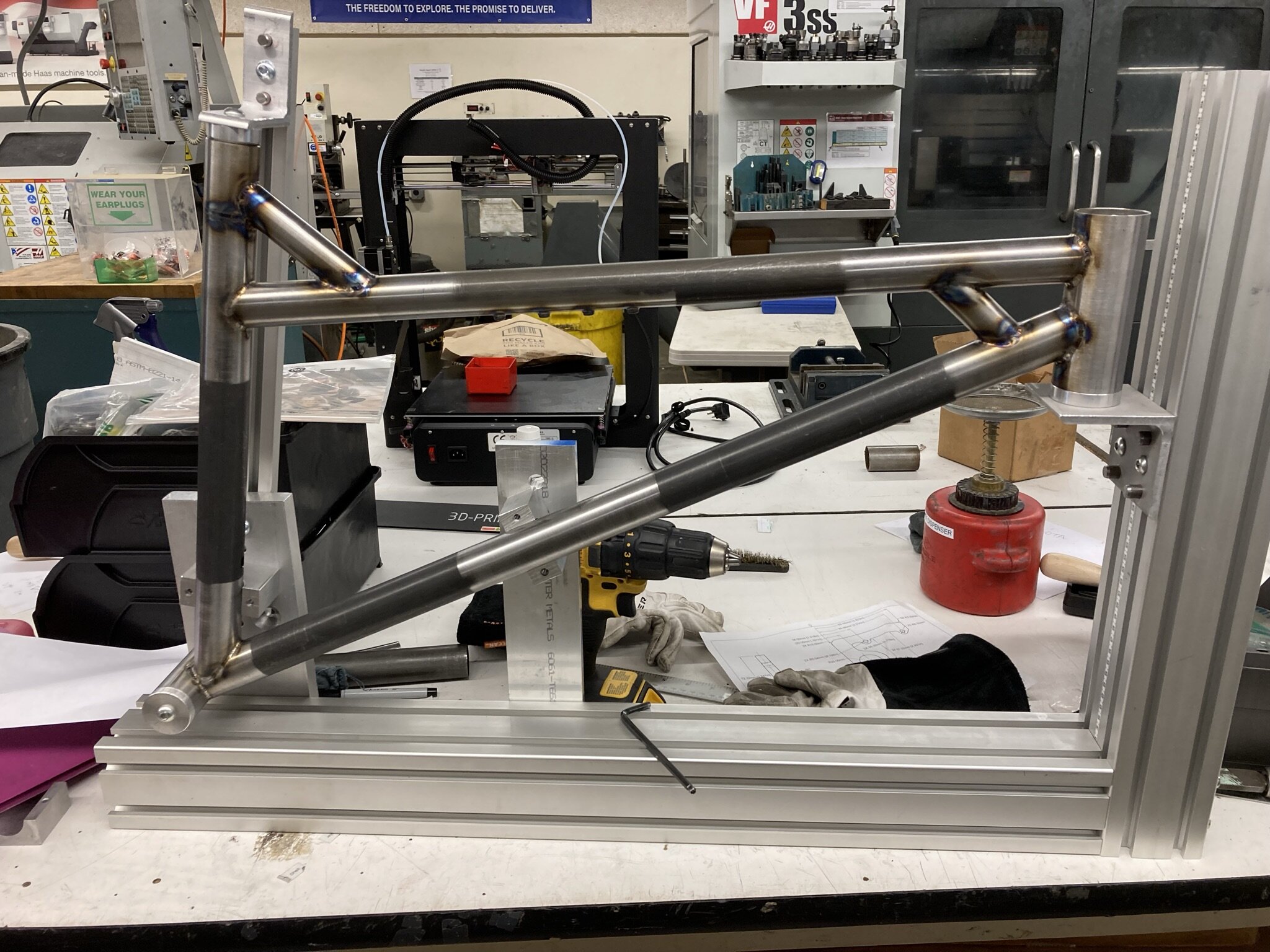
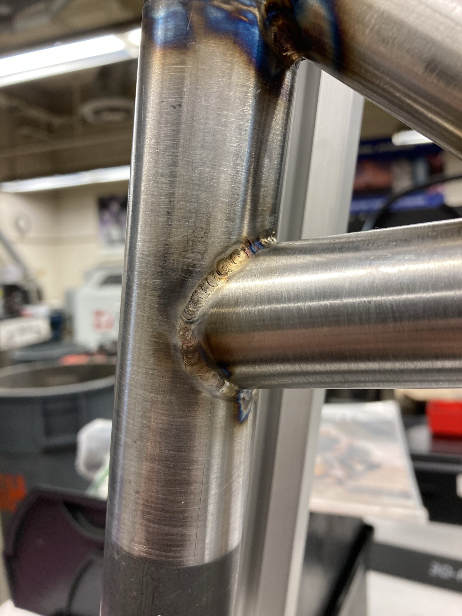
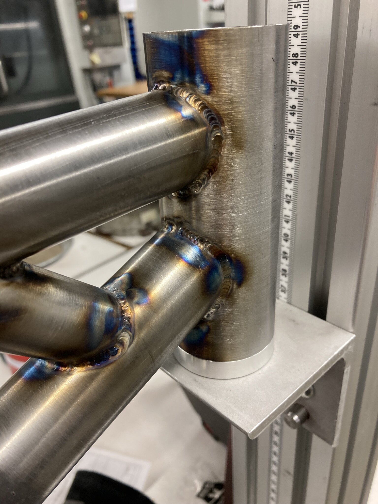
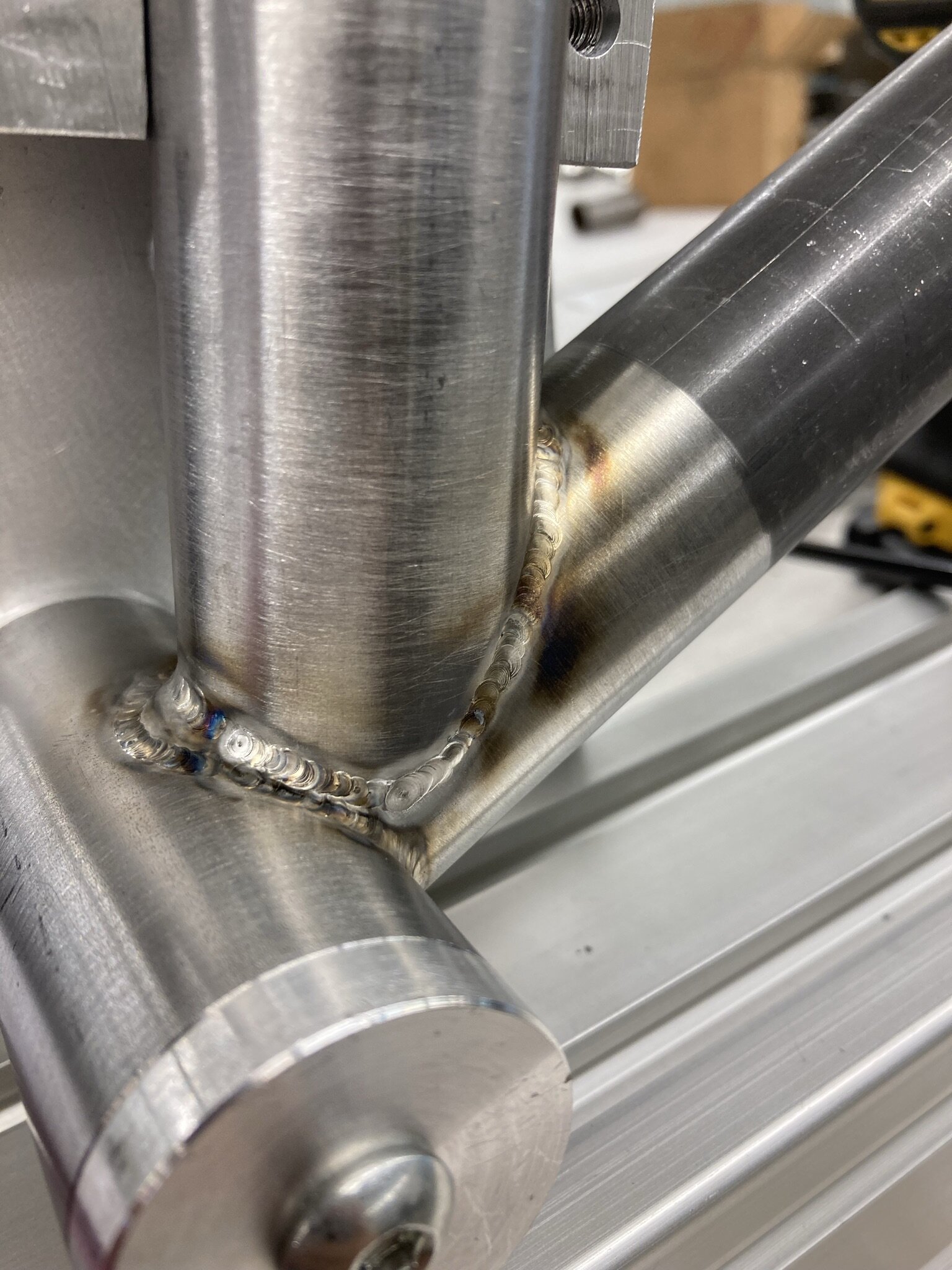
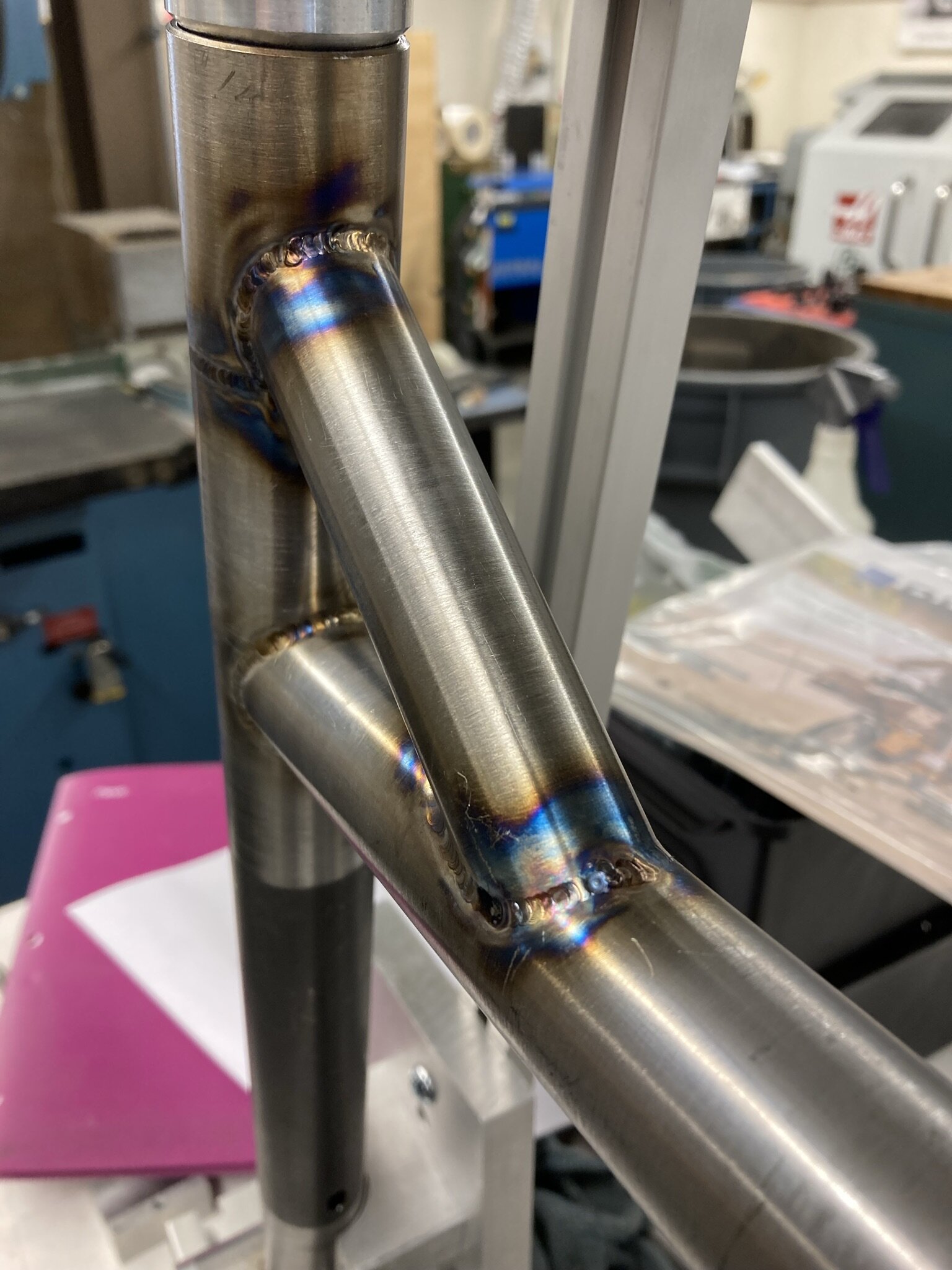
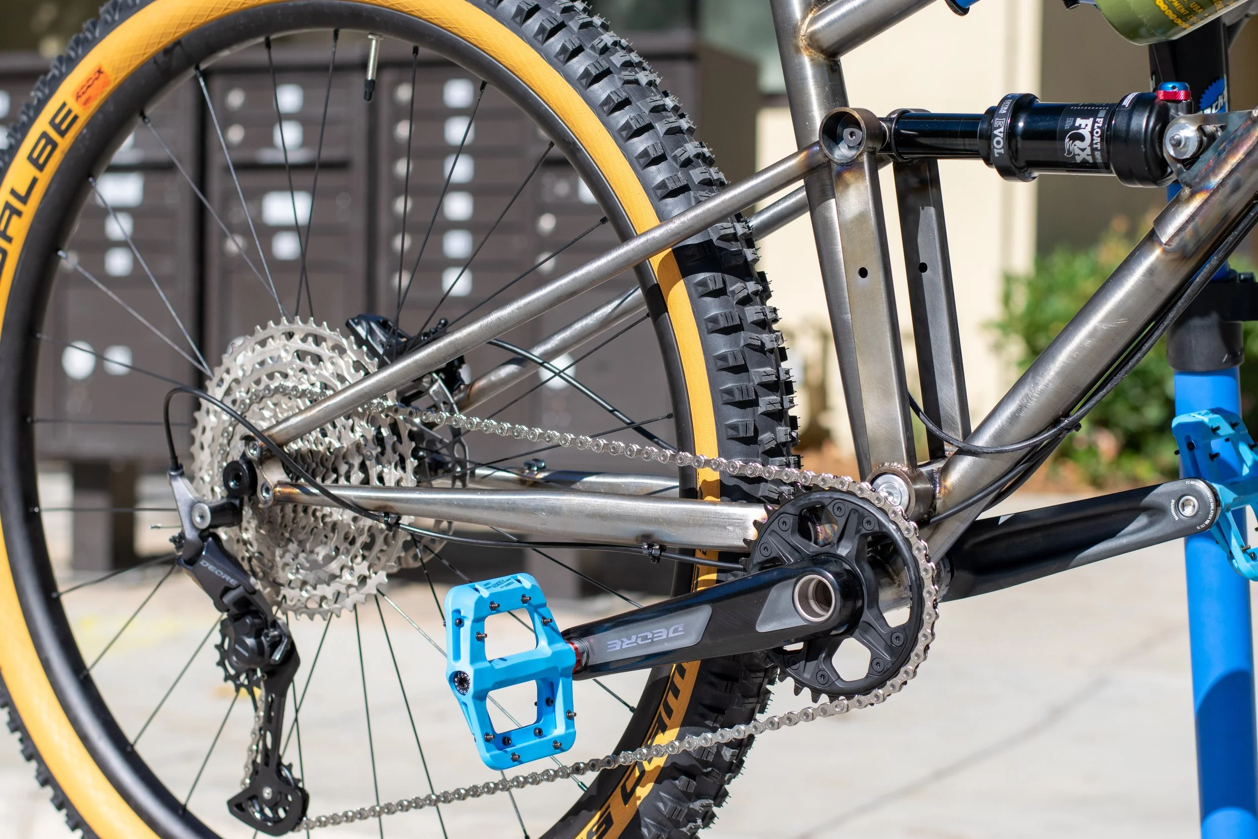
Frame Photos
Here are some photos of the welded frame prior to component installation. I decided to clear coat the frame in order to preserve the “raw” look of the sanded metal and heat-affected zones.